*Please click video title headings to play video if video does not load properly.
Why does the coil in d.c. motor keep rotating in same direction?
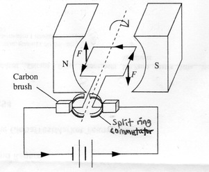
In the diagram above, based on Fleming’s left hand rule, the right side of coil experiences an induced force in downward direction while the left side of coil experiences an induced force in the upward direction. This creates a clockwise moment about the pivot (axis of the coil) and coil rotates in clockwise direction.
At every half a turn, the direction of current flowing in the coil reverses direction. This is because when the coil is at the vertical plane position, the split ring commutator is not in contact with the carbon brushes and no current flows in the coil. However, the inertia of the turning coil keeps the coil rotating past the vertical plane position and the contact between split ring commutator and carbon brushes is re-established while the direction of current flowing in the coil will be reversed.
The reversal of the direction of current in coil every half a turn ensures direction of induced forces on the right side and left side of coil will remain unchanged, keeping the coil in clockwise moment rotating in same clockwise direction.
Simple DC Motor Demonstration
The following video shows a simple DIY DC motor which can be easily constructed using things like copper wire, paper clips, magnets and batteries.
This video shows the factors affecting the speed of rotation of the coil. Increasing the strength of magnet used, number of turns of coil or voltage of battery used will increase the speed of rotation of the coil. The strength of magnet is changed by putting the magnet closer or further away from the coil. The number of turns of coil is changed by winding different number of turns of wire in the coil while voltage of battery is changed by using different batteries with different voltages.
Note that this DIY set-up may look slightly different from the DC motor in the physics syllabus, but it actually works on exactly same principles. It requires a magnet with a magnetic field surrounding the coil. In this video, only one magnet is used and put at the bottom of the coil to set up a magnetic field. However, we can also set up two magnets with opposite poles on both sides of coil as found in your textbook to set up a magnetic field passing through the coil (or see the diagram for DC motor in the post right on top). Who says there must be only one single way of doing things?
As for the split ring commutator and carbon brushes set-up, it may seem missing in this video, however at time 1:12 of the video, it is explained that one end of the coil has half of its curved surface along its length insulated while the other half is exposed copper wire. This DIY set-up provides similar effect as the split ring commutator and carbon brushes in cutting off the current in the coil every half a turn when the paper clip touches the insulated portion and there are no induced forces acting to prevent causing a counter moment on the coil that opposes the original turning moment. The inertia of the rotating coil will make the paper clip touch the exposed copper wire on the other half curved surface again resulting in induced forces acting on the coil once more in same direction on each side of the coil after one complete turn. This ensures the coil continues to rotate in the same direction. <Actually, there is an O level question from ten years series (year 2003 Paper 2 Qn 7) that already asked on such DIY set-up which questioned why there is a need for half of the curved surface along the length of one end of the coil to be insulated?>
In understanding the working of DC motor, there are 3 important hurdles to cross:
1. Knowing how to derive the direction of the induced forces on both sides of the coil using Fleming Left Hand Rule.
2. Appreciating the need to cut off the current flow in coil every half-a-turn when in the vertical plane position and then re-establishing the current flow in the coil again such that the direction of current flowing in the coil is reversed when the split ring commutator and carbon brushes re-contact again. Make sure you can visualise the reversal of current in the coil once the current is re-established. Do not believe what others say until you really try to visualise the coil turning past the vertical plane position and seeing for yourself that the current flowing in the coil has indeed reversed its direction.
(A method I find useful is to denote each of the four corners of the coil with letters A, B, C and D and trace the flow of current through the four corners at the start and again after the cutting and reconnecting of current flow again after the coil turned past the vertical plane position to see that the current flow which was originally flowing A-B-C-D but after the cutting and reconnecting of current flow, the direction of current flow is now reversed in D-C-B-A direction through the coil bearing in mind the letters assigned to the four corners of coil must be always in their fixed positions while the coil turns.)
3. Based on the necessary reversal of direction of current flowing in the coil, again use Fleming Left Hand Rule to see for yourself that even as right side of coil has now become left side and vice versa, the induced forces acting on both sides of the coil remain in their same directions.
In conclusion, only direction of current flowing in the coil keeps reversing direction every half-a-turn due to cutting off and reconnecting of circuit with use of split-ring commutator and carbon brushes set-up. The direction of induced forces acting on both sides of coil certainly will remain unchanged as a result of the constant reversal of current every half-a-turn. If not, how can the coil continue to rotate in same direction always by common sense since the induced forces on both sides of coil must give the rotation?
